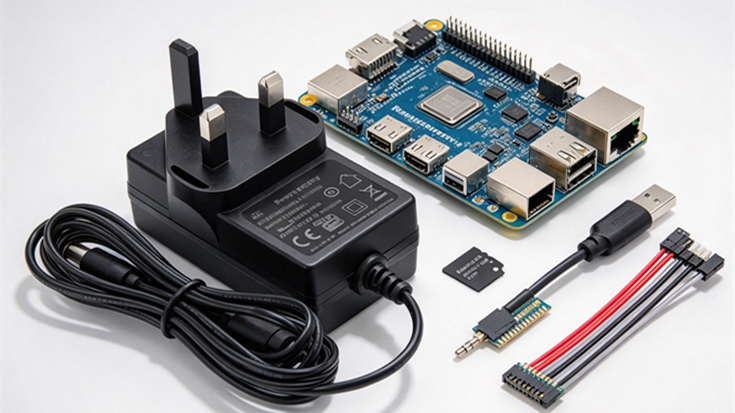
The Technical Cause: Why 5.0V Is Not Enough for Raspberry Pi 4B
Standard USB chargers are designed to maintain 5.00V at the power block’s output terminals. However, when driving a 3A load over a 1.5-meter cable, significant linear voltage drop occurs due to wire DC resistance.
Voltage Drop Calculation Across 1.5M Cables
The mathematical equation governing cable loss under full load is straightforward:
Vdrop = I × Rcable = 3.0A × 0.12Ω = 0.36V
If a conventional 20AWG or 22AWG cable is used, total resistance often exceeds 0.18Ω, resulting in a cable loss of Vdrop ≥ 0.54V. At 3A full load, the voltage reaching the Raspberry Pi mainboard plunges to 4.46V.
Board-Level Under-Voltage Thresholds (≤ 4.63V Warning)
The Raspberry Pi PMIC (Power Management IC) monitors the 5V rail constantly. When the incoming voltage dips below 4.63V (± 0.05V), the firmware immediately limits CPU clock frequencies to prevent memory corruption, displaying the low-voltage warning icon. Under heavy compute loads or peripheral activity, voltage dips further, leading to sudden reboots.
How 5.1V Nominal Output Compensates for Line Loss
By specifying a nominal output voltage of 5.10V DC combined with 18AWG heavy-gauge pure copper conductors (≤ 0.12Ω/1.5m), maximum line loss is strictly capped at 0.36V. This guarantees a terminal voltage at the Pi board of ≥ 4.75V under full 3.0A load, completely eliminating under-voltage throttling.
Key Technical Specifications: 5.1V 3A PSU vs. Official SC0218 Benchmark
Below is a direct comparison between generic commercial phone chargers and an industrial-grade Raspberry Pi 4B dedicated power adapter built to match the official SC0218 specification:
| Specification / Test Metric | Generic 5V/3A Phone Charger | Custom 5.1V/3A Pi4 PSU Standard | Engineering Rationale |
|---|---|---|---|
| Nominal Output Voltage | 5.00V DC (±5%) | 5.10V DC (≥5.10V at 3A load) | Offsets cable impedance to prevent under-voltage throttling. |
| Cable Gauge & Impedance | 20AWG ~ 24AWG (>0.18Ω) | 18AWG Pure Copper (≤0.12Ω) | Minimizes copper loss under 3A sustained continuous load. |
| Type-C Connector Architecture | Contains E-Marker IC | Dummy Type-C (No E-Marker IC) | Bypasses Pi 4B Rev 1.1 CC pin hardware bug (prevents no-boot). |
| Over-Current Protection (OCP) | Strictly capped at 3.0A | 3.3A ~ 3.6A (Hiccup Auto-Recovery) | Absorbs transient inrush current during SSD startup without shutoff. |
| Energy Efficiency Grade | DoE Level V / Unrated | DoE Level VI / CoC Tier 2 | Avg. efficiency ≥81% (25%-100% load); Standby power ≤0.075W. |
4 Critical Manufacturing Pitfalls to Avoid for E-Commerce & Amazon Compliance
When engineering a third-party adapter for commercial production or e-commerce distribution (e.g., Amazon, eBay, Shopify), failing to adhere to these four rules will lead to product returns, hardware incompatibility, or legal listing removal.
Avoiding Trademark Infringement: Logo & Branding Rules
Rule: Strictly prohibit the use of the official Raspberry Pi logo, trademarked graphics, or official branding on the adapter’s plastic casing or packaging. Use clear, compliant language such as “Power Adapter Compatible with Raspberry Pi 4B” to avoid trademark infringement takedowns on retail platforms.
Eliminating E-Marker Chips to Prevent No-Boot Issues
Rule: Early Raspberry Pi 4B mainboards (PCB Rev 1.1) featured an improper CC pin design where CC1 and CC2 were tied to a single ground line. Smart USB-C cables equipped with E-Marker ICs misidentify the board as an audio accessory and refuse to supply power. Utilizing a pure Dummy Type-C connector without E-Marker ICs ensures 100% plug-and-play compatibility across all Pi 4B hardware revisions.
Setting OCP Margins (3.3A–3.6A) for High-Power Peripherals
Rule: Over-Current Protection (OCP) must NOT trigger at or below 3.0A. High-performance USB 3.0 expansion boards, NVMe SSDs, and active cooling fans demand transient peak inrush currents (3.2A–3.4A) during boot. Setting the OCP threshold between 3.3A and 3.6A with hiccup auto-recovery prevents immediate power shutoff upon boot-up.
Specifying 18AWG Pure Copper Cable for Minimal Impedance
Rule: Never downgrade the wire gauge to 20AWG or thinner to reduce costs. At 3A continuous draw, 20AWG wire causes excessive IR drop across a 1.5m length, rendering even a 5.1V power brick ineffective at the board terminal.
Factory Quality Assurance & Inspection Standards (IQC/FQC)
To ensure zero-defect production runs and long-term operating stability, every production batch must undergo a 5-step quality assurance protocol:
2-Hour Continuous Full-Load Aging Test at 3A
100% burn-in testing under continuous 3.0A load at 40°C ambient temperature. Output voltage drift and thermal rise are monitored to ensure structural thermal stability.
SSD Startup Peak Inrush Impact Testing
Automated power-cycling tests connected to NVMe SSD loads to verify that peak transient currents do not trigger premature OCP latching.
Terminal Voltage Verification
Direct voltage probing at the Type-C male terminal (end of the 1.5m cable) under full 3.0A load to confirm terminal output remains strictly ≥ 4.75V DC.
Quad-Protection Testing (OCP, SCP, OVP, OTP)
Validation of four key protection circuits: Short Circuit Protection (SCP hiccup), Over-Current Protection (OCP 3.3A–3.6A), Over-Voltage Protection (OVP 5.7V–6.0V latch), and Over-Temperature Protection (OTP at ≥ 110°C shell temperature).
Dynamic Load Transient & Ripple Noise Verification (≤ 100mVp-p)
Load step transitions from 0.5A ↔ 3.0A with electronic loads. Transient voltage dips must remain ≤ 0.25V, with full-load ripple and noise held under 100mVp-p.
Need Custom 5.1V 3A Power Solutions for Raspberry Pi Projects?
OEM/ODM Manufacturing Capabilities
Developing reliable power solutions requires precise engineering, strict copper wire sourcing, and robust circuit protection. We manufacture high-efficiency power supplies, GaN chargers, and dedicated industrial power adapters tailored to demanding embedded applications.
Request Samples & Technical Data Sheets
If you require custom housing design, private label packaging, or technical documentation (UL 62368-1, CE-EMC, FCC, DoE Level VI), feel free to reach out to our engineering team for technical consultation and sample evaluations.